Click on any picture to enlarge. Click again on the picture to shrink it down again.
This work was carried out during a full louvres replacement contract. If you are interested you can see more on that part of the work at THIS LINK.
When we removed the old louvre windows the steeple was, for the first time in years, filled with sunlight. Also, the removal of the louvres at either end of the bell cradle exposed some steelwork that we had not been able to see previously. At this point it became extremely obvious that there was a serious problem with the bell suspension components. The bell was not far away from falling, and if it had there is a very good chance it would have gone through the top floor (and possibly the 3 floors beneath too). It may not have stopped until it reached ground level.
Pretty much 100% of bells that are suspended from a timber headstock (and this one is) are attached to the headstock with 3 separate hangers. The central one is always a U-bolt, and the 2 on either side can be U-bolts or an arrangement involving vertical flat bar hangers and bolts with which they engage at the bell shackle level. This bell had a U-bolt and vertical flat bar hangers.
The flat bar hangers were completely corroded away. The U-bolt was the only thing that was holding the bell and the tips of the U-bolt, at the point where it met the nuts, were corroded down from their original 16mm to about 4mm. One easy turn with a shifting spanner (once the bell was independently suspended of course) was enough to shear the tops of the U-bolt and release the bell from the last of its original suspension.
The picture below shows all the hangers.
The U-bolt is indicated by the blue arrow.
The vertical flat bar hangers are indicated by the red arrows.
The U-bolt looks fine here because the narrowed parts are concealed by the metal immediately below the nuts, but look at the vertical flat bar hangers. They have corroded so badly that they have fallen off at some point in the past.

Here you can see the tips of the U-bolt once we had separated it from the bell shackle. The arrows indicate the narrowed tops that sat just below the nuts. The silvery shine on top at both ends is newly sheared metal (it sheared with very little force). They were all that was stopping the bell from falling.

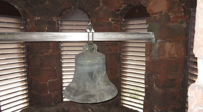
Another picture of the bell suspension components before work started.

You can see a lot of the timber bell cradle here. All of the timber was soft and no longer fit to carry the weight of that bell.

At some point in the past the dangerous condition of the bell suspension bolts, and timber cradle, had been noticed, and a job had been done to support the bell and prevent it from going through the floor when the original suspension compenents inevitably failed.
The only problem with that was that the steel RSJ (Rolled Steel Joist) beams installed had never been painted, at least not for many years, and so they were rusted to the stage where their strength was gone.
You can clearly see that this RSJ has been placed underneath the bell to support it’s weight. You can also clearly see how destroyed the metal was by corrosion.

But the worst part was the RSJ prop that was supporting this end of the main RSJ. Look at the bottom of it. The web (vertical part) has separated from the flange (horizontal part). It was also extremely unstable. A very gentle touch was enough to set it swaying from side to side.

We built a temporary but strong scaffold derrick to enable us to lift the beam. From this we suspended a heavy duty pull-lift, and this allowed us to get the weight of the bell off the original suspension components and begin removing them.

It was quite a lot of work to cut up all of the timber bell cradle and the RSJ beams and lower everything to ground level. This picture was taken during that phase. As you can see it’s controlled chaos at this point.

A view of the chaos from above.

Once we got all the mess out of the bell chamber we had to cut pockets into the stone to carry the new suspension beam. Here you can see one of the pockets during the cutting phase. We have a laser level pointing from one pocket to the other as it helped us to be sure that we were cutting in at the correct angle (the red lines are from the laser).

The beam inserted into the wall pockets. We specified stainless steel for the beam and the suspension U-bolts. It costs a bit more to do this, but it means that the new suspension arrangement is maintenance free. It doesn’t need painted – ever, and it will never rust and become dangerous.

Taking templates for the new stainless steel U-bolts. We used lightweight bendable rod to get the shape. Once we had this it was a simple matter to have a local engineering company create the parts.

Measuring up.

Bell now fully suspended from the new components. 20mm diameter stainless steel U-bolts attached to a very strong 150mm x 150mm stainless box section beam.

A view from below.

Note how much cleaner the bell is. After doing so much work to make the bell safe, and tidying up the bell chamber so much, we decided to wire brush the pigeon guano off the bell itself. It’s not perfect but it looks a lot better than it did.

This picture shows quite a bit of the bell chamber as well as the bell. Nice and tidy in here now.

We also installed the louvres and mesh, and the link to that work is HERE (just click).